Lunar Rover Cockpit Ergonomics Study
Significant gaps in experience, technology, and mission definition from Apollo to Artemis necessitate a renewed approach to Lunar Roving Vehicle (LRV) architecture. The aim of this project was to study the Apollo LRV cockpit with respect to human factors considerations and determine possible ergonomic improvements. A task analysis defined cockpit functions, relevant literature and standards, including the original LRV design, were reviewed to identify anthropometric constraints. Next, a criticality analysis established the operational significance of selected cockpit elements. Leveraging the insight gained from this research and subsequent analyses, ergonomic changes were recommended to the Apollo LRV cockpit configuration. The expected outcome of these changes is increased astronaut productivity and comfort during future long- range surface EVA.
This work was completed as a group project for ASEN 6519: EVA at CU Boulder in Spring 2021 with Dr. Allison Anderson. Our full final report can be found here.

Apollo LRV control panel
Since future EVA operations on the Moon will build on heritage systems, the Apollo Lunar Roving Vehicle (LRV) serves as an appropriate reference for the vehicle system architecture. Though much has changed since the Apollo era in terms of available technology, the high-level capabilities of the Apollo LRV are in agreement with the general desired capabilities of a future unpressurized rover. The objective of this human factors study is to recommend ergonomic improvements to the LRV cockpit layout. The ergonomic parameters chosen to guide layout decisions are 1) work/reach envelope and 2) look angles/view distance.
The Apollo LRV control and display layout (image left) was kept simple and contained in two main interfaces. The instrumentation panel was centered between the two seats and contained all displays and controls. The T-handle joystick was sized and shaped to be operated with bulky spacesuit gloves and handled all vehicle motion control without the addition of pedals or other levers typically found in automobiles on Earth. The joystick controlled acceleration, turning, reverse motion through a switch, and could lock into a parking brake configuration if the LRV needed to stop on a slope.
Functional Task Analysis

Baseline design requirements are built up from a hierarchical operator task analysis (OTA). Such an analysis decomposes complex tasks into a “hierarchy of operations and sub-operations with the aim of identifying those that are likely to fail due to poor design or lack of expertise.” This is just one kind of task analysis and is most pertinent to this study as rover operation is the primary concern. Rover OTA offers a means of investigating a nominal mission thought to be typical of that expected from a future lunar EVA, not unlike a detailed concept of operations (CONOPS). While many of the analyzed operations are beyond the scope of this design, they establish context and justification for the assumptions of what elements should be included in the cockpit.
Posture, Work Envelope, View Angles

Seated Posture. We generally considered 3 orientations (left) for seating posture, evaluated pros and cons of each, and ultimately settled on an approach similar to the Apollo LRV.

Work Envelope. Measured from the rover seat centerline, each astronaut’s work envelope extends 22 inches forward and spans 62 inches horizontally. These bounds are the practical reach limits of each astronaut while seated, which is one of the ergonomic parameters driving subsequent cockpit layout analysis.


Look Angles. Field of view and look angle analysis seeks to accommodate the 5th to 95th percentile astronauts. When viewing the bottom, middle, and top of the dashboard, the 95th percentile male had a view angle approximately 10 degrees greater than the 5th percentile female, potentially creating view issues with information near the bottom of the display.
Combining the horizontal and vertical view angle analysis yields design considerations for how to logically organize information in the display. In the horizontal direction, it is easiest to view information on the near side of the dashboard. However, astronauts can view information in the center of the console with the same effort, making it an optimal place to put critical information. In the vertical direction, more critical information should be placed toward the top of the display to minimize the view angles for the range of astronauts.
Proposed Cockpit Layout
Developing a cockpit layout in the absence of a vehicle in which to locate it presents difficulties and reduces the validity of the unconstrained final solution. Since an updated model of the Apollo LRV would serve as a reasonable contender for satisfying the Artemis rover RFI requirements, it serves as the conceptual and literal chassis for this work. Once these baseline dimensions were established, the existing LRV design is able to be evaluated in terms of the selected ergonomic criteria: look angles and distance, and work and reach envelopes.
The work envelope, developed above, is overlaid on the rover drawings and the look angles and distances are computed numerically. This analysis reveals slight deficiencies in the design, with regard to NASA STD-3001, that have emerged over decades as spacesuit technology has evolved and the range of accommodated body sizes has expanded. Though the dashboard console is within acceptable view angles and distances, some of the key controls are just beyond the work envelope.
The proposed updates to the cockpit layout, shown in red, involve a minor relocation of the dashboard console and joystick to move both into the astronauts’ work envelope for the full range of EMU-suited body sizes, from a 5th percentile female to 95th percentile male. The 6.72 in. adjustment seems like an almost insignificant change, but in the already tight quarters of the rover and under the strenuous conditions of operating the vehicle during an EVA, even a small change can dramatically improve astronaut comfort and reduce fatigue, which can improve EVA productivity, temperament, and safety.


Dashboard Layout
The work envelope calls for locating switches and buttons requiring manual operation being closer to the astronauts, so these are located along the bottom of the angled console. The high-frequency, most critical displays are located near the top of the display, minimizing look angle and distance and keeping them within the field of view of a driver who is focused on the rover’s surroundings. The Master displays and controls, consisting of power on/off, resets, and alarms, are centrally located and prominently sized to assure that they cannot be ignored. These control elements are also intentionally a slightly further reach distance, due to their infrequent use and a desire to reduce inadvertent operation.
As with the Apollo LRV, the dashboard is centrally located to aid in manipulation by either astronaut. Vertical orientation better suits both work envelope and look angles by containing controls horizontally, and reduces impediments to rover ingress and egress.
Precise design of individual displays, types and operation of switches, and to some extent the sizes of different elements, is left ambiguous as these are beyond the scope of the layout study. However the relative sizes and groupings of different functions provide a visual hierarchy reflecting criticality, with like functions grouped together and critical, higher frequency interaction elements larger.
Lunar Ice Prospecting Mission
The above EVA task analysis can be applied to a mission ConOps of a crewed ISRU prospecting mission. Given a target site, possible basecamp location, EVA suit performance for two astronauts, and an unpressurized Apollo LRV-style rover, this study sought a maximum safe travel distance for the mission.
We utilized maps for Ice Favorability Index (IFI) and terrain slope from the LOLA instrument aboard LRO to determine potential target sites and routes. The approximately 45 km round trip required for the mission is slightly more than twice the distance covered by Apollo 17’s EVA 2, which included four planned and eight minor stops for a 7 hour and 39 minute EVA, which ended approximately 40 minutes behind schedule. Allowing 3 hours for each LRV traverse and 90 minutes for on-site geology activities creates a 7 hour and 30 minute total EVA, with some margin programmed into each phase of the mission, and an overall allowance of 30 minutes to arrive at 8 hours total.
A worst-case hazard is an LRV failure upon reaching the mission site, creating a 20+ km, 10-hour walkback starting midway through an already long EVA. This suggests the need for a rescue mission capability, most likely from a second LRV, which could reach the site in under 2 hours in an emergency with consumables replenishments or transport back to the habitat. If the EVA astronauts are still mobile, walkback could begin and meet a rescue LRV, further reducing rescue time. Assuming a rescue LRV can transport one EVA astronaut at a time while the other continues to walk back, the last rescued astronaut would be returned to the habitat approximately 6 hours after rescue begins. If the rescuing LRV driver allows both EVA astronauts to return on the rescue rover, total rescue time is much reduced, though the rescuing astronaut would still need to be recovered.
The recommendation from this analysis is that, for long-distance missions, spare consumables (oxygen) should be carried on the rover, and that a second vehicle may become necessary for support and rescue missions.
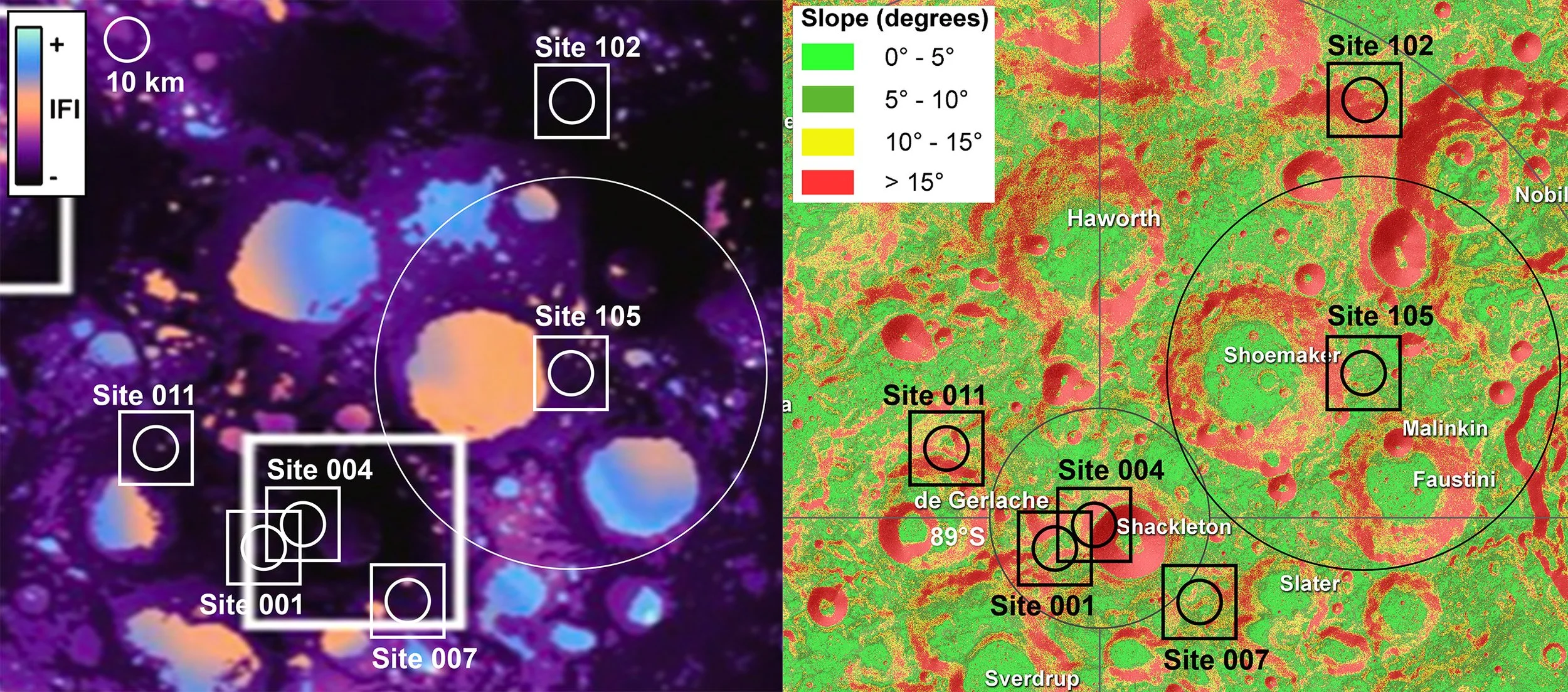
Landing site selection at the Lunar South Pole, superimposed on the IFI map (left) and terrain slope map (right), produced from data from the Lunar Orbiter Laser Altimeter (LOLA) aboard the Lunar Reconnaissance Orbiter (LRO) by NASA’s Goddard Space Flight Center.

Estimated path for this mission, assuming a slope-minimizing route for a 20-km straight-line path.