HLS ECLSS Research & Design
The purpose of the HERD Project is to develop an Environmental Control & Life Support System (ECLSS) for Northrop Grumman’s Lunar Human Landing System (HLS). NASA’s requirements for HLS call for a series of 5 design reference missions (DRMs) that can be distilled into two key reference missions: a 6.5-day equatorial surface stay with 2 crew and a 31.5-day polar surface stay for 4 crew where the lander serves as transport to a pre-placed habitat. HLS must also support a high EVA cadence, with up to five 8-hour EVAs during the shorter ‘sortie’ DRMs, and must integrate with the Gateway HALO module and Orion crew module.
The HERD team is responsible for developing subsystems for atmospheric pressure and revitalization, temperature and humidity control, cabin ventilation, crew safety, and wastewater control. My focus on this project was the Flow & Ventilation subsystem and leading the CFD studies in ANSYS Fluent, but I also worked on temperature and humidity control, crew safety, and atmosphere pressure control.
This work was completed as part of ASEN 6028 Graduate Projects at CU Boulder. Our project advisors were Stuart Tozer and James Nabity and the project was sponsored by Northrop Grumman. The 2023 ICES Paper is here.
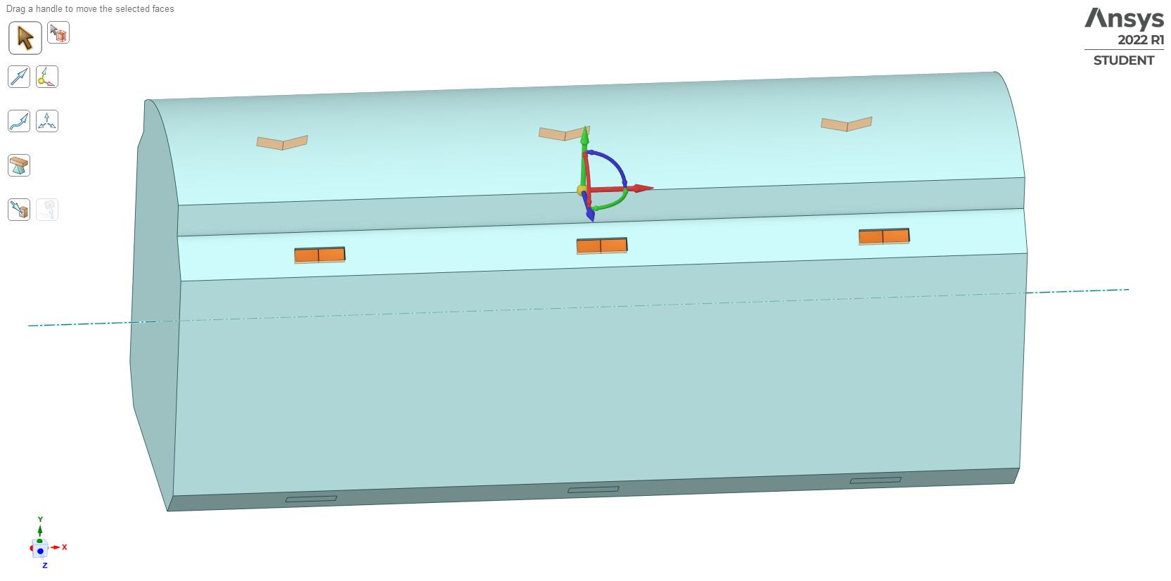
Habitable volume (green), equipment zone (orange), and an early duct and vent layout of the HLS ascent module.
Ventilation Subsystem Design
The purpose of the ventilation subsystem is to ensure adequate airflow throughout the habitat to transport oxygen, humidity, carbon dioxide, airborne contaminants, and particulates. Work focused on developing conceptual equipment, register, and ducting layouts, utilizing 3D CAD and computational fluid dynamic (CFD) modeling to verify the key driving requirements. The analysis work focused on determining a needed airflow rate through fluid simulations, sizing and locating registers, and sizing and selecting a fan that can meet the determined rate. The system has three key driving requirements:
The HLS shall maintain a ventilation rate within the internal atmosphere such that two thirds of the atmosphere velocities are between 4.57 m/min and 36.58 m/min (0.076 - 0.61 m/s) (HLS-S-HMTA-0019)
The HLS shall limit the levels of microbial contaminants by maintaining a continuous flow of air (HLS-S-HMTA-0051)
The HLS shall limit the levels of lunar dust particles between 0.02 and 10 μm in size in any habitable cabin atmosphere (HLS-S-HMTA-0047)
The system is principally concerned with three key metabolic outputs in the cabin atmosphere: heat, moisture (exhaled and perspired), and carbon dioxide (CO2). These outputs will quickly move their associated parameters outside the range of environmental requirements if the ventilation system does not transport them out of the cabin and to their respective revitalization subsystems.
CFD Study
My focus was developing a robust CFD study to verify the design of the ventilation system against the cabin flow requirement. This included fan sizing, inlet and outlet register size, shape, orientation, and location, and supporting equipment and ductwork layout.
The habitat model developed is a low-fidelity “surrogate” model that assists compute resources and allows for generalization of findings. Generation of the model included the following assumptions.
Inlets defined as velocity or mass flow
Outlets defined as zero pressure
Side walls and floor assumed to be equipment cabinets with heat flux of ~100-200 W/m2
Nothing modeled inside the cabin, including crew
Lunar gravity: 1.625 m/s2
Exploration atmosphere of 8.2 PSI in the cabin
Inlet air temperature: 285 K (53°F)

3D Model instances in Rhino/Grasshopper
Cabin model imported to ANSYS SpaceClaim from Rhino/Grasshopper
Vents. The vents are bi-directional and angled outward by 15° on each side, as well as angled up into the clerestory portion of the habitat by 20° to resolve the airflow dead spots encountered in earlier studies. The overall vent size changed several times during the semester and is 10x30 cm (~4x12 in.) in the final iterations. This is likely the largest plausible vent size given the possible range of duct sizes, and future development may need to reduce the size of these vents, increasing outlet velocity to achieve the same airflow. Register locations also varied throughout different design studies, but eventually settled to 3 inlets and outlets mirrored in the cabin.

Typical mesh quality in Fluent, with localized sizing at registers and cabin walls.

Design and layout of ventilation registers and supporting ductwork. Ductwork is intended to be a placeholder rather than actual design.
Heat Flux. As an ancillary investigation to establishing flow rates, the simulations also make possible the addition of thermal loading into the cabin atmosphere. In this case, two of the walls and the floor in the cabin are assumed to have an associated heat flux.
The International Standard Payload Racks (ISPRs) on the International Space Station are allowed to emit up to 500 W of heat into the cabin atmosphere beyond what is removed by the cold plate system. If this comes from the front (interior) face of the rack, this translates into approximately 240 W/m2. HLS is assumed to have smaller equipment cabinets, be less densely packed with equipment, and unlikely to carry more than a handful of in situ science experiments, so this heat flux value is assumed to be a maximum of 200 W/m2 beyond what is handled by the internal thermal control system.
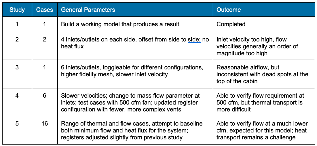
Study Results
Simulation work was organized into five studies throughout the semester and one or more cases within each study. Since early studies were equally focused on learning Ansys, building a plausible working simulation model, and finding the best ways to display results, only the outcomes from the last two studies are included below.

Fluid flow results with the color scale constrained such that the requirement range of air velocities is captured by all colors between dark blue and dark red.

Best and worst heat transport results, temperature heat maps of the cabin walls and a longitudinal section of the cabin, along with associated average cabin temperatures.

Airflow cases, where 100 W/m2 heat flux was held constant and ventilation rate varied from 500 to 100 cfm. The cabin comfort zone is shown in green on the left.

Heat transport cases, where ventilation is held constant at 500 cfm and heat flux varies from 200 to 25 W/m2.
The final set of study cases sought to address two questions: what is the minimum airflow that will satisfy the flow requirement in the cabin, and what is the greatest heat flux that the system can accommodate?
Airflow Cases
The first plot on the left and first set of path line images above show cases where equipment wall heat flux is held constant at 100 W/m2 and inlet air is always 285 K, but the airflow rate varies from 500 to 100 cfm. As the path line images show, all but the two lowest ventilation rates likely satisfy the requirement, and the 200 cfm level may. However, all but the 2-3 highest flow rates fail to adequately transport heat away from the cabin atmosphere.
Heat Flux Cases
In these cases the ventilation rate is held constant at 500 cfm while the equipment wall heat flux varies from 200 to 25 W/m2. In most cases the make-up air is kept at 285 K, but one case explores the effect of lowering it to 280 K (44°F). We can extrapolate this effect across all heat flux cases (orange line in the plot) since results are so linear, suggesting some heat levels can be moved into the comfort zone by fine-tuning this parameter. The challenge with this approach is crew comfort near inlets.
Conclusions
Airflow requirement verified. A 500 cfm fan easily handles ascent stage ventilation and could likely go as low as 250 cfm and still meet the requirement. However, adding a descent stage to the model increases habitable volume by ~50%, suggesting a ~400 cfm fan could be sufficient. This result has positive implications for interfacing with Gateway segments, such as HALO and Orion, where minimal ventilation could potentially be supplied in an emergency.
Heat transport is not really sufficient, given the stated assumptions. Even at the highest flow rates, the system can’t handle the 200-220 W/m2 range of heat flux. At around 125 W/m2 and >400 cfm, it can get into the comfort range, especially if makeup air temperature comes down by a few degrees.